hra fb twitter
sheffield
header

Main Cylinders

First First Previous Previous uparrow Back to Index Next Next Last Last
143 records found. Page 14 of 15 displayed.

For most of the photos on this page, you can click the image for a larger picture.

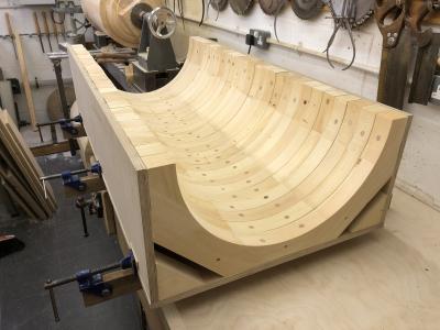
Highslide JS With all of the core sections fitted temporarily into the box, the core box is starting to take shape. next job will be to fit the end pieces. Remember that this core box will be used to create a solid "tube" of moulding sand which will sit in the "prints" of the main pattern.
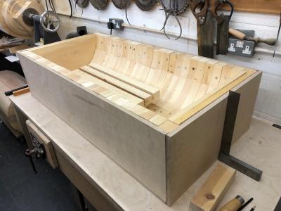
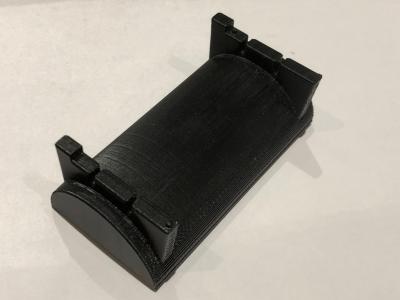
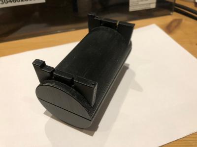
Highslide JS This is the core box for the main cylinder nearing completion. It just needs cleaning up now. This core box will be used to produce 2 semi circular cores which will be joined together to make the complete core for the cylinder. The "1a" core is a simple semi circular core whereas the "1b" core will be more complicated as it will need 2 additional cores to provide for the transfer ports at each end of the cylinder. The bit of wood for this work are in the bottom of the core box. Tony is aiming for the same core box to be used for both cores.
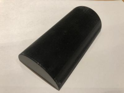
Highslide JS This is core "1a" which will sit in the bottom quarter of the mould and is a simple semi circle. In the photo, it is upside down.
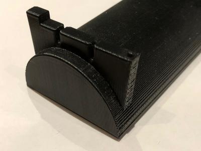
Highslide JS This is the end of core "1b" which will sit above core "1a" and shows the transfer port cores. The transfer port cores will need to engage in locating holes in the 1b core made by the 'prints' added to the 1a core
Highslide JS This is the full "1b" core with the transfer port cores at each end
Highslide JS This is how cores "1a" and "1b" are combined to provide the full core for the main cylinder. The valve cylinder core will be more complex as it has a series of annular rings within the cylinder
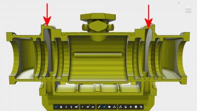
Highslide JS Tony's next job is to build the core box for the valve cylinder. The image shows the cross section through the valve cylinder. Whereas the main cylinder (below the valve cylinder) is a relatively simple tube containing one piston, the valve cylinder has a more complex internal section. The valve cylinder contains a piston rod with 2 piston heads. These oscillate around the transfer ports to the main cylinder - arrowed. You can see that there are 3 internal diameters and Tony will need to make jigs for all 3. In contrast, on the main cylinder, Tony only needed one jig as the cylinder is a constant diameter. Then horizontal bar in the centre allows the whole piston assembly to be removed. If the bars weren't there then the piston rings on the rearmost piston head (as it was being withdrawn) would spring out and prevent the assembly from being removed.
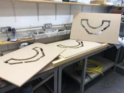
Highslide JS Here are the 3 jigs, each of a different diameter.
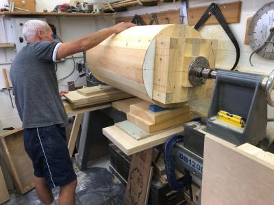
Highslide JS Tony now has the second half of the valve cylinder pattern onto his lathe. Here is Tony's neighbour helping him to set it up. The pattern needs to be carefully balanced as there is a lot of weight in the pattern
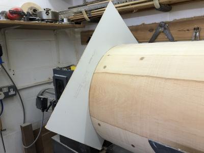
Highslide JS Tony now has the second half of the valve cylinder pattern on his lathe. After some slow speed running to get the pattern balanced, Tony can start work to turn down the complete pattern to an eighth of an inch above final size. Here he is using a templated to confirm sizing is correct.
First First Previous Previous uparrow Back to Index Next Next Last Last
143 records found. Page 14 of 15 displayed.